

Macsusc
-
Posts
242 -
Joined
-
Last visited
-
Days Won
14
6 Followers


Macsusc's Achievements
")


-
 Always happy to give it to a long term member, thank your for supporting us for so long!! ❤️ @auxiliry06 Our automatic delivery system will now send an email every 2 days to notify you about the win for 2 weeks so you can claim it in the delivery management dashboard! Thank you 🙂 If you missed it, watch it here!
 -
-
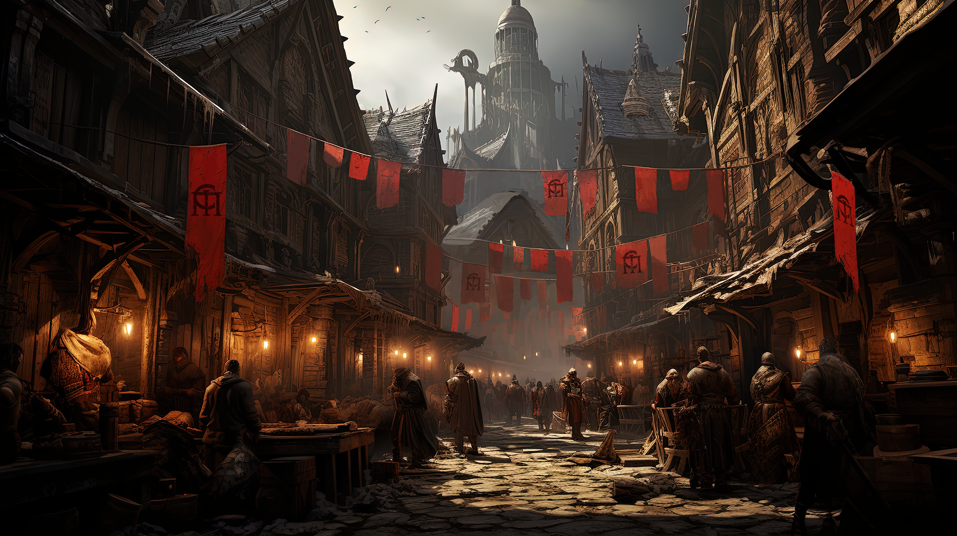
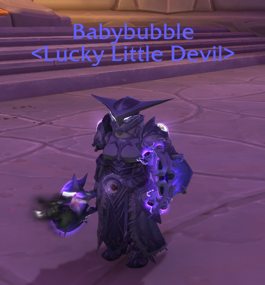
Floor is Glass is Giveaway Game where we people can Freeble. Everyone players as a Lucky Little Devil. Anyone can host a game. Once players enter the lobby, they can choose a tile to stand on. Every round, the host can click "Go" which allows players to move up, down, left or right. - Each round, random glass tiles will crack. - After three cracks in the same tile, the glass will break - Any lucky little devil standing on a tile which breaks, gets eliminated. Last man standing wins. Since this is a Freeble game, we want to make sure a giveaway always happens, so if everyone is eliminated together on the last round, the game will choose someone randomly from the final group which is eliminated. Host a game here -> https://www.thecrimsonmarket.com/giveawaygames Or come join us on the next Twitch stream (3PM CST Every Saturday) to win some moooooooooney 🙂 (We've given away over $9000 USD in games just like this on our stream so far!)
-
-
Addon Update & Leaderboards are live with Giveaways
Macsusc posted a blog entry in World of Warcraft's Guild News
Hi everyone, I had to rebuild the addon, the way data syncs in WoW with addons made it unfeasible to create what I first imagined. However, I think this will be much easier to understand and I have built something even better for us. The addon has a new update so please install it through CurseForge and check it out. We will now handle all giveaways through the leaderboard and milestone system. -
Freeble (noun, verb, adjective) Pronunciation: /ˈfriː-bəl/ Plural: freebles Verb forms: freeble, freebling, freebled Definition Freeble (noun) A game, event, or system in which participants can win real rewards without paying to enter or risking money, assets, or anything of value. Freeble (verb) To participate in or host a zero-cost, zero-risk reward game. Freeble (adjective) Describing an activity, system, or reward model that allows winning without financial risk. Core Meaning A freeble represents a new category of play that combines the excitement of winning with complete financial safety. Unlike gambling, a freeble involves: No entry fee No wagering No possibility of loss Unlike traditional gaming, a freeble includes: Real-world rewards Tangible outcomes for participants Etymology Derived from the word “free” (no cost, no restriction) combined with a suffix inspired by “gamble,” forming a term that represents risk-free reward-based play. Usage Examples “I entered a freeble and won a gaming PC.” “We’re freebling a $10,000 prize this weekend.” “This platform runs daily freebles for its users.” “That’s a freeble system, not gambling.” Key Characteristics A system qualifies as a freeble if it meets all of the following: Zero Cost Entry Participants are not required to pay money or purchase anything to enter. Zero Financial Risk Participants cannot lose money, assets, or value. Real Rewards Outcomes include tangible prizes such as cash, products, or digital assets. Fair Participation Winners are determined by chance, skill, or a transparent combination of both. Comparison Concept Entry Cost Risk of Loss Rewards Gambling Yes Yes Yes Gaming No No Usually No Giveaway No No Yes Freeble No No Yes Related Terms Freebler (noun): A person who participates in freebles Freebling (noun): The act of engaging in a freeble Freeble Event (noun): A scheduled opportunity to participate in a freeble Freeble System (noun): A platform or mechanism designed to host freebles Notes The term freeble defines a distinct category separate from gambling due to the complete absence of financial risk or required payment. It emphasizes accessibility, fairness, and reward without loss. Summary Freeble is a modern term for a system of play where anyone can participate freely and win real rewards, combining the excitement of winning with the safety of zero risk.
-
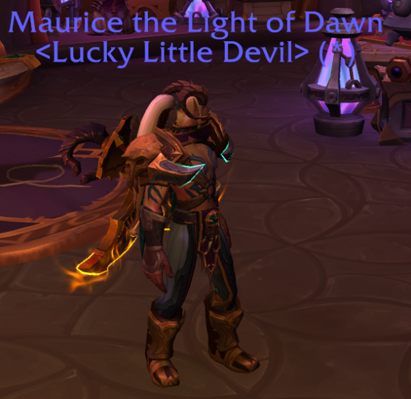
image_2026-03-05_225338985.png
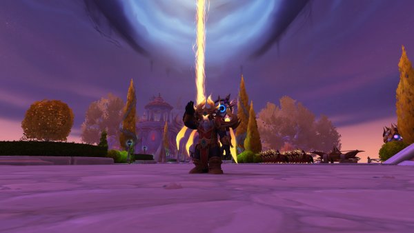
Macsusc commented on Elisian's gallery image in World of Warcraft's Transmog Giveaway
 You need better lighting.
 -
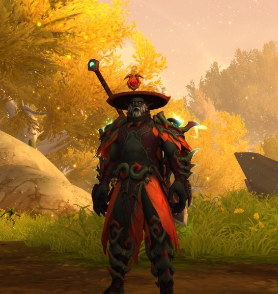
 NGL, this one is a straight up alien and the matching weapons etc, it's a good vibe.
 -
 mashiro this is the set from the midnight heroric edition xD - I appreciate the participation, thank you ❤️
 -
 I just unlocked the Haranir, the druid forms make me want to reroll xD
 -
Youtube Giveaway - Social Riddle is LIVE
Macsusc posted a blog entry in Feedback & Updates's Updates
Hey everyone, We have another giveaway system that people can take advantage of to help grow their socials and we're kicking it off with a $1000 USD giveaway. Grow your socials by introducing hidden words in your videos which commenters need to guess, there is a campaign studio where you can set everything up, choose your words, hints, how many videos there are in a chain and more. Check it out and below and if you want to win the $1000, remember to Play With Purpose! 🙂 https://www.thecrimsonmarket.com/socialriddlegiveaway/ -
until
<- DPS - Hunter -
untilRSVP and then reply in comments with your ROLE to solidify your position, there will be a $50 giveaway at the end of the raid where people get put into a wheel where the size of their slice is based on their performance and we will spin to win!
-
Kris Kringle - Black Box - For Family & Friends
Macsusc commented on Macsusc's raffle in Public Raffle
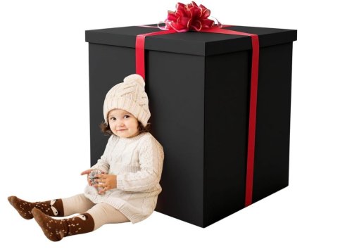 Thank you for the videos! I am so happy to finally put a computer in one of our long term members hands and am glad it was done through the additional Kris Kringle on New Years we randomly thought of haha! Now we are playing WoW together xD !!!
 -
Hibernator PC
Macsusc replied to Cat_Dad8311's topic in PC Giveaway Community's Build & Technical Help
I just sent you another 75 to cover it man, you deserve to have that computer working and entertaining you.