


AlmightyWaffles
-
Posts
19 -
Joined
-
Last visited
-
Days Won
1
Content Type
Profiles
Forums
Downloads
Events
Store
Gallery
Blogs
Articles
Videos
Recipes
Raffles
Everything posted by AlmightyWaffles
-
Hibernator PC
AlmightyWaffles replied to Cat_Dad8311's topic in PC Giveaway Community's Build & Technical Help
Hello everyone, I'm genuinely puzzled by this situation. The PC had been assembled and running smoothly for quite some time before I entered the BIOS to adjust a few settings, including enabling XMP—all with the side panel secured in place. During the build video for this PC there is a point where I talk about the clearance between the CPU cooler and the side panel. It's possible that some shifting occurred during transit, which may have affected the internal components. The case itself could have sustained some deformation from being laid on its side or from the weight of items placed atop it. Please check out the link below to the build video to refer back to. https://www.youtube.com/watch?v=lFc2I5plKw8 @Cat_Dad8311 — I'm delighted to hear it's up and running for you now. Please enjoy this gift from all of us at The Crimson Market, and thank you for your continued membership -
Hibernator PC
AlmightyWaffles replied to Cat_Dad8311's topic in PC Giveaway Community's Build & Technical Help
I 100% agree with @Macsuscassumptions. Those are the exact steps I would undertake to try to rectify this issue. @Cat_Dad8311Honestly mate, there's no need to worry. Nothing on a PC can't be repaired or replaced. Sometimes it takes a few steps to ascertain the exact issue, but we will figure it out and get this PC going for you. -
Hibernator PC
AlmightyWaffles replied to Cat_Dad8311's topic in PC Giveaway Community's Build & Technical Help
Next step would be 1. Test RAM Individually Remove all RAM sticks except one Try that single stick in each RAM slot one at a time If it works in one slot but not others, you may have a bad slot If none work with that stick, try a different stick If after trying both modules in every slot and the DRAM light is still not working, then it is a strong possibility there is something wrong with the RAM. However I still doubt this to be the issue, as RAM is usually a pretty solid component in a PC. -
Hibernator PC
AlmightyWaffles replied to Cat_Dad8311's topic in PC Giveaway Community's Build & Technical Help
The DRAM indicator light signifies an issue with the RAM modules. As an initial troubleshooting step, I recommend reseating the RAM. Begin by removing the fan assembly shown in the image above. Next, locate the RAM sockets and press down on the retaining clips at the top of each socket to release the modules. Carefully remove the RAM sticks, noting their original positions. When reinstalling, ensure the pins on the modules align correctly with the socket notches. Apply firm, even pressure to seat the RAM until the retaining clips snap securely into place around the modules. -
Hibernator PC
AlmightyWaffles replied to Cat_Dad8311's topic in PC Giveaway Community's Build & Technical Help
Hey guys, this is a very interesting situation, as it was posting for you and now doesn't, I would check IF the GPU had come loose a little bit in transit, and just finally fell that mm more where it wont connect now? Can you please send/upload an image of the internet of the PC, focusing mainly on the GPU, also I believe that Motherboard should have debug lights, if you could get an image of them for me too please. That would be great. -
Hibernator pc
AlmightyWaffles replied to Cat_Dad8311's topic in PC Giveaway Community's Build & Technical Help
@Cat_Dad8311Hi please find a DM from me about this issue. Sorry for this inconvenience. -
Hi truly sorry for the late reply on this, was away for Christmas. I am sending you the invoice through a DM now.
-
Since the fans don't spin at all when the PC is booted on, then it extremely likely to be either the internal fan power connector on the PCB or the card's fan control circuitry must be defective, now due to the item still being under warranty, the next step is to send the GPU itself back to the manufacturer for RMA (Return Merchandise Authorization), where they would determine whether or not it is able to be fixed or if it just needs to be replaced.
-
Gday, this sucks to hear you're going through this DaWalrus. Now firstly, I would start by installing MSI AFTERBURNER, and seeing if the fans will spin if forced to. If you have used MSI Afterburner to force the fans on your brand new XFX Swift Radeon 9070XT to a set speed (e.g., 50% or 100%) and they still do not spin, this strongly indicates a hardware issue or a software conflict. Which could mean either there is a conflict of power between AMD Adrenalin and MSI Afterburner, or since the card is brand new and software control is failing, the fans themselves, the internal fan power connector on the PCB, or the card's fan control circuitry might be defective. A key indicator of this is that the fans likely do not spin briefly when you first boot your PC. Do the fans slightly spin, or move at all when you first power on the PC?
-
UEFI Boot shell
AlmightyWaffles replied to DaWalrus's topic in PC Giveaway Community's Build & Technical Help
@DaWalrus Gday Mate, I have sent you a DM about this issue, please reply at your convenience, thanks. -
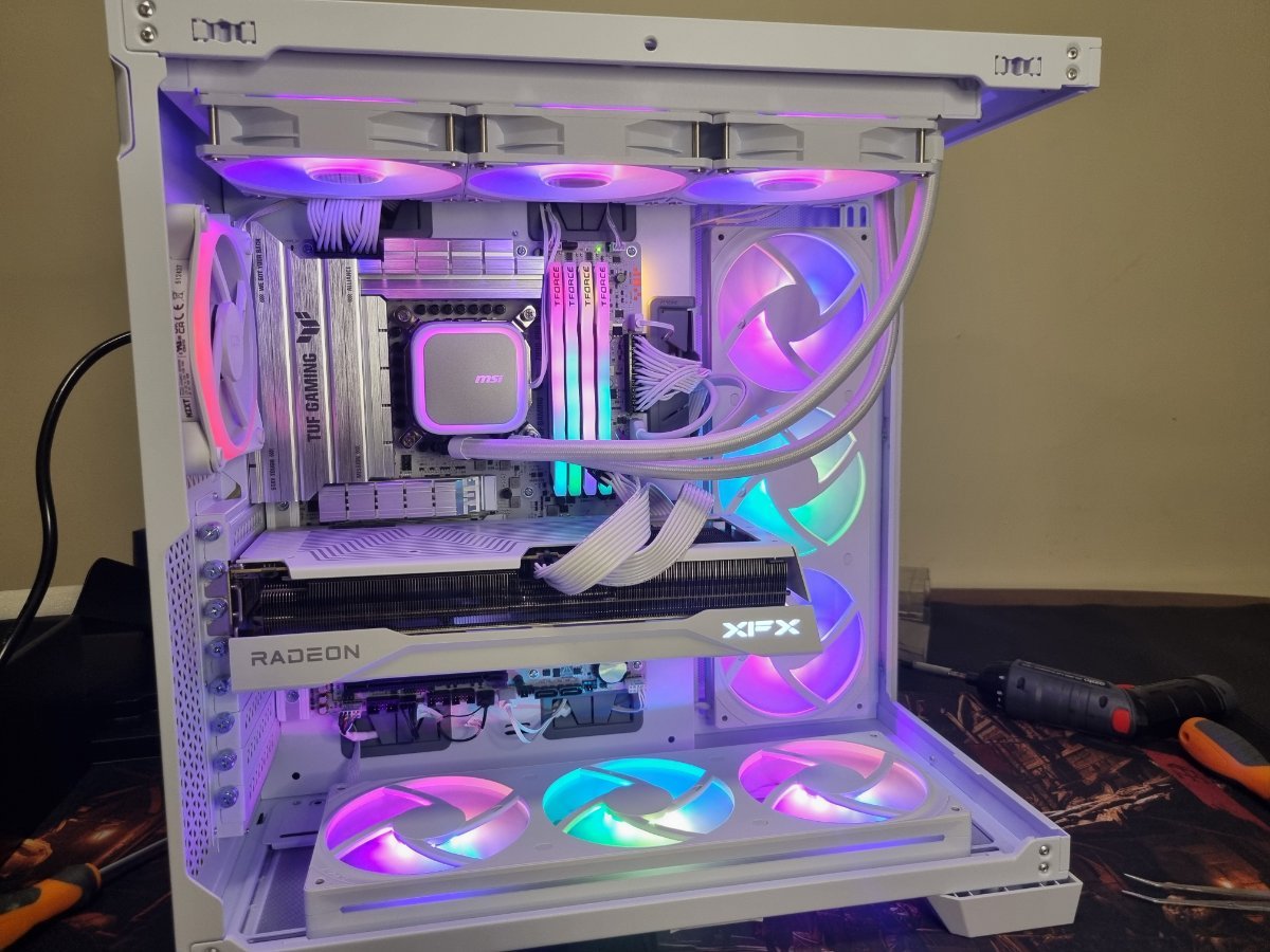
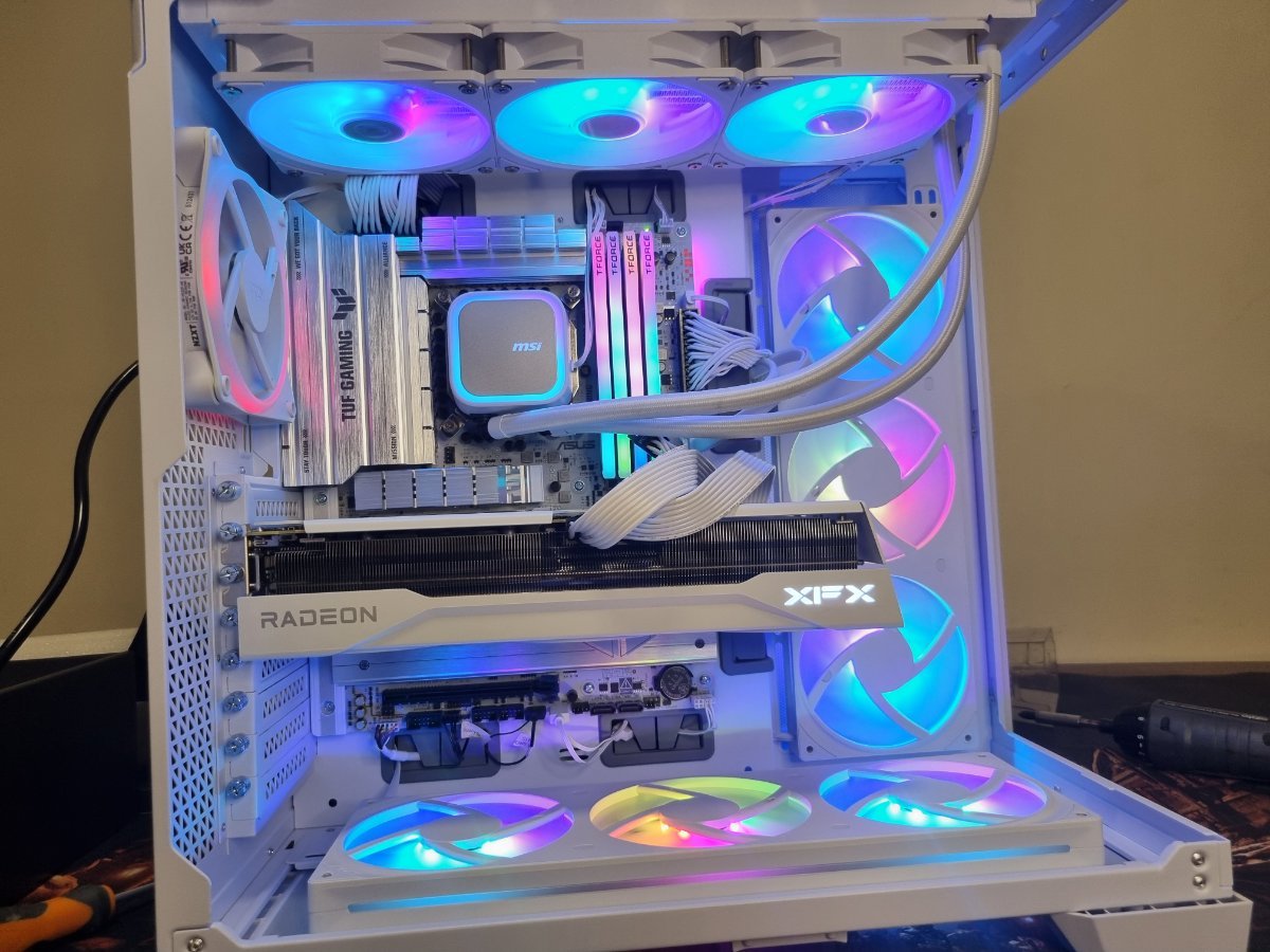
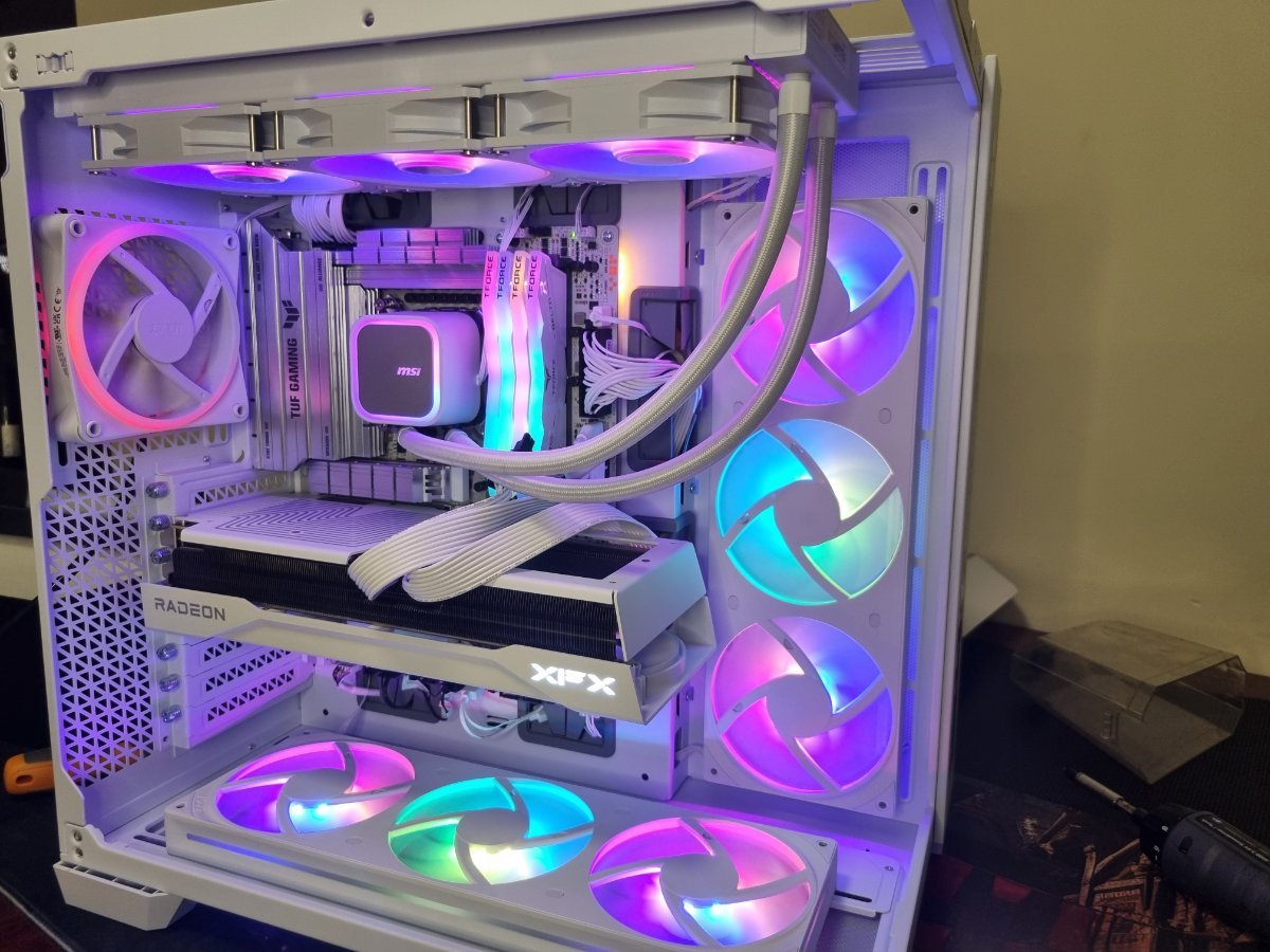
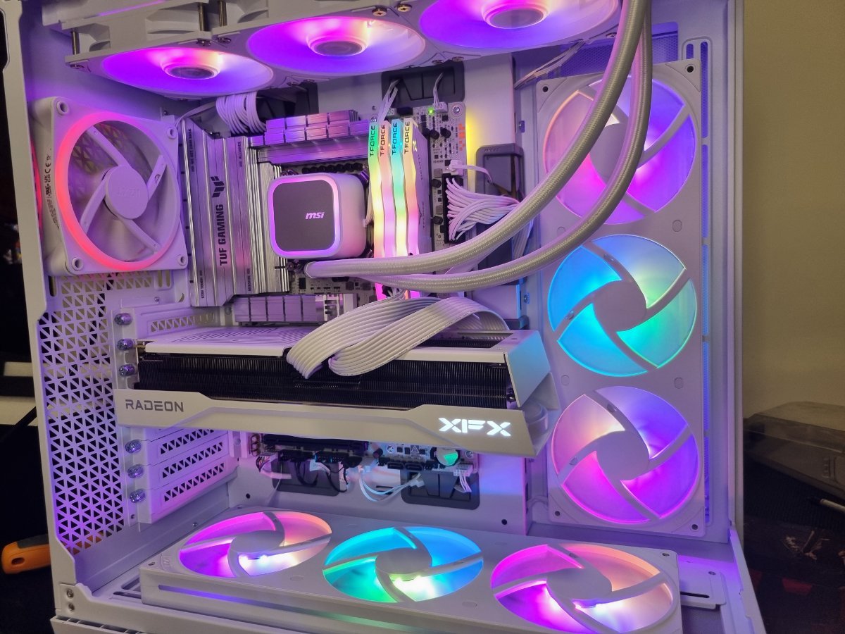
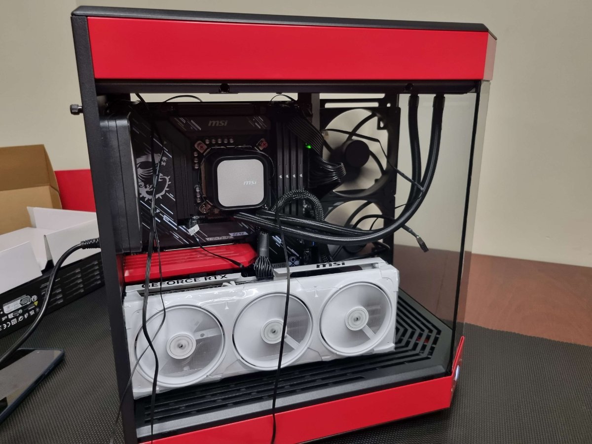
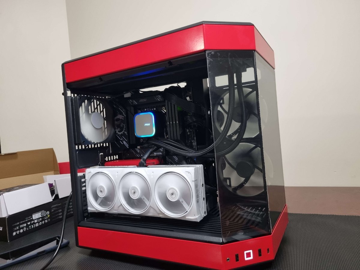
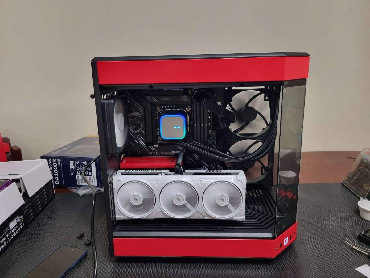
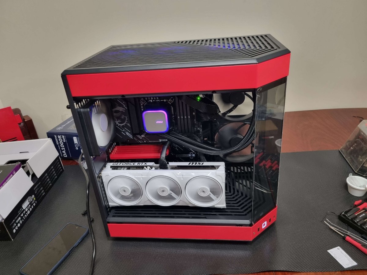
Step 1: Alright so first of all, we start by grabbing out the Motherboard, CPU, RAM, M.2 and the backplate for the CPU Cooler. Step 2: Now that we have all of that out and ready, we install the CPU first. So I had to open the CPU socket, then install said CPU making sure the triangles in the corner line up. Step 3: Now it was time for me to remove the M.2 heatsink cover from the motherboard, and install the M.2. Which with this case was completely toolless. After the M.2 was installed, I undid the 4 clips on the RAM sockets, and installed all 4 sticks of RAM into the Motherboard. Step 4: Easy step now, all I had to do was remove the sticky cover from the CPU Backplate, line it up with the screws and push down against the piece. Only slightly so that it contacts with the back of the motherboard and sticks there. Step 5: Alrighty, now it was time for me to prep and install the Power Supply. Firstly was to plug in, the 24 pin, 2 8-pin CPU power, 2 8-pin PCIE power cables, and the 1 sata power cable. Alright, next step was to turn the case around, and install the Power Supply into the back of the case. Step 6: I was now at the time to install the Motherboard into the case, so I grabbed the 9 necessary screws and did just that, lining the IO shield to the back of the case Step 7: Okaly Dokaly, the next step was to install the AIO CPU cooler. Now I'm going to start by grabbing it out, making sure the fans are in the layout I was wanting (they were). Now that I was ready, I grabbed the Radiator and fans, and installed them into the top of my case, securing it with the 12 included screws. Step 8: It was now time to apply some Thermal Paste to the CPU, and then install CPU cooler. So that's what I did, I applied some Thermal paste in my traditional "X with dot" pattern. Step 9: Now one of the most tedious parts of building a PC has arrived, cable managing. So I quickly installed my fan hub into the bottom of the back of the case, by removing one of the unused SSD bays. I then started running cables, and managing exactly where I wanted each cable to go. This was an absolutely long job, probably almost 2 hours, getting ALL the cables exactly where they would look best. Step 10: Now the time has finally arrived, to install the funnest and usually most expensive part into a PC, the Graphics Card. Now this is an easy part, but it really just ties together an entire computer. So with the Graphics Card installation, and the 2 8-pin PCIE cables plugged in, I had a completed computer. Step 11: This step was just about turning it on, and making sure it power cycles and boots, which no issues of course.

-
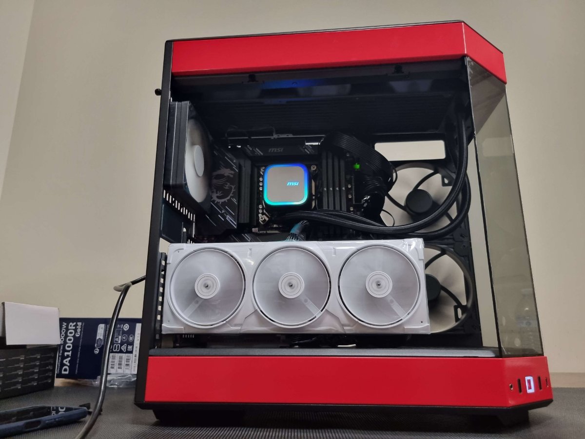
Crimson PC Build Log Step 1: Alright guys so here we are for the Crimson PC, so first of all, we start by grabbing out the Motherboard, CPU, RAM, M.2 and the backplate for the CPU Cooler. Step 2: Once we got all that out, we start by opening the CPU socket bracket, and inserting the CPU into the slot, ensuring that the triangle on the Motherboard and CPU are aligned up, now I actually couldn't find said triangle on this particular Motherboard, I'm sure it was there I was just unable to find it, so I just to line the pins on the Motherboard to the pins on the CPU. Step 3: Next to install was the M.2, so I had to remove the M.2 heatsink/cover so that I could install it. Now with this board in particular it was completely tool less, I undid the button slip on the left side of the cover and it popped straight up, now I instert the M.2 into the slot and turn the pre installed tool less clip that holds it down. Once completed I removed the plastic off the thermal pad on the inside of the cover and reinstalled it. Step 4: Now I was ready to get my RAM installed with was easy enough, the board has 4 slots and I was using 4 sticks, so no need to check the manual to find which slots were for dual channel. I then undid the clips on the end of each of the 4 Ram sockets on the motherboard and installed them 1 by 1, ensuring along the way that my sticks were aligned to the orientation of the socket. Step 5: This step was quick and easy, I grabbed the backplate for the CPU cooler, and removed the plastic from the double sided tape it uses to stick to the motherboard. I flipped the Motherboard over, and installed it onto the back of the CPU socket. Step 6: I then grabbed out my Power Supply and the necessary cables for this computer, now I didn't realize this at this point but I will point it out, the Motherboard we used actually needed 2 8-pin EPS power cables for CPU power and a dedicated 8-pin PCIE power cable for PCIE power. So I used those cables, a 24-pin, a 600w Graphics and a Sata power cable. Once I had them all installed, I was able to install the Power Supply into the back of the case. Step 7: I was now at the time to install the Motherboard into the case, so I grabbed the 9 necessary screws and did just that, lining the IO shield to the back of the case. Step 8: Now it was time to grab my AIO CPU cooler and get it ready for installation. So to start doing this, I removed the Radiator mount from the top of the case, by undoing the 6 screws on top and pulling it out. Once I had that removed, I was ready to install my Radiator and fans to the mount. Now here's where things get interesting, I tried to mount the Radiator on top of the mount with the fans on the bottom, but this was impossible. The provided space for the tubes coming out the Radiator to go, were not big enough to fit this Radiator. So after installing it all once that way, I had to remove it and place the fans on top of the mount and the Radiator on the bottom. Step 9: So this is where I was ready to install the Graphics Card, or at least I thought I was ready. I installed the Graphics Card to find out, that all the Motherboard cables like the fan headers and the ARGB headers were all behind where the Graphics Card was to sit. So I then had to remove the Graphics Card and start plugging in the cables. Step 10: At this point I have realized that the Motherboard had only 6 fan headers and I was going to need 7. So I went and grabbed a PWM fan hub and installed this into the back of the case. I actually installed it into the hard drive bay (due to only using m.2 on this build that space was completely unoccupied) Step 11: Now that I have rectified the issue of not enough fan headers, I went back to plugging in all my cabling and sorting out the best runs for them to look neat in the computer. Finally after doing all this, I was finally ready to reinstall the Graphics Card. Step 12: Now that the Graphics Card is back, I have finally got completely build computer and am ready to plug in and turn on. Here we go, I plugged her in and unfortunately one of the fans were not spinning, so I had to turn it back off and reseat (just basically unplug it and plug it back in) and turn it back. This time the fan was spinning and the computer was fully working Step 13: So now all that was left was to plug it in and install windows. I also played with a couple of the settings in the bios to get the best performance from this computer.
-
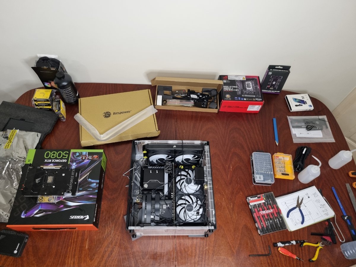
Kintsugi Build Log Step 1: Alright so I started by grabbing the motherboard out and placing it on it's box Step 2: I then opened the CPU socket on the motherboard and whilst making sure the arrows in the corner lined up, installed the CPU into it's socket. Then I closed the socket with the lever, popping off the cover in the process Step 3: Next step I did was grab my CPU water block mounts and installed them into the motherboard, after that I then applied the thermal paste to the CPU and screwed on the water block. Step 4: I grabbed my 4 sticks of ram and installed them in the ram slots. Step 5: Then I grabbed out my case, laid it down and removed the side panel. (The next step was done out of instinct as it's the way I have usually build PC's, however I would 100% recommend you do this step after you have installed the Power Supply into the included Powerboard and then into the case) Step 6: I then installed the motherboard into the case, using the cases included mounting screws. Step 7: I then had to install the Powerboard onto the Power Supply, however this was easier said than done, let me explain. The sheer amount of force that it took to install was unbelievable. I had to use all my might to make sure every connector was 100 percent inserted. I thought it was quick and easy to install, but after close examination I found that the connectors werent going in without me forcing them. Step 8: Once I had it completely inserted I had to get the Power Supply and Powerboard installed into the case. On the backside of the case there was a small hook shaped bracket that needed to be removed as well as a Power Supply cover bracket. Got both of them out, and now had to get the Power Supply in. At this moment I realized this case actually had another bracket on the bottom of the inside of the case, this bracket was to be preinstalled onto the Power Supply prior to its installation in the case. I unscrewed the 2 screws holding this bracket into the case and installed the bracket onto the Power Supply. Step 9: Now that I have rectified the bracket issue, I can finally install the Power Supply into the case, and this is where my issue I mentioned earlier arose. Installing the Power Supply with the Motherboard already installed was almost impossible, I had to kind of angle it into place, where the Powerboard would slot into the mentioned hook shaped bracket. Once I had that lined up, I was able to screw the bracket I had previously installed onto the Power Supply to the bottom of the case. Step 10: At this point I was ready to start working on the Radiators, both of which were 240mm and required 2 fans installed onto each prior to their installation into the case, so that's what I did, I then went to install the radiators into the case and quickly found out that the screws that came with the radiator (which are long enough to go through a standard metal frame case which is usually only about 2 or 3mms thick) were not long enough to go through the thicker acrylic on this case. So I had to go and get some M4x10mm bolts (12 of them). Once I had the necessary bolts, I then installed the radiators to the case. Step 11: Alright so at this point, it was starting to look like a computer but with a very messy birds nest of cables everything, so I took a little bit of time moving the cables around and connecting the 2 fans of each radiator together, daisy chain style and plugged them into the Powerboard. I also grabbed the included 24 pin and 8 pin ribbon cables that came with the case, and got them installed into the Powerboard and Motherboard. Step 12: Now this is where another issue arose for me, I was so quick to get things installed into the case, I forgot that this case comes with a touch screen button and that the cable wasn't installed into the case yet, I so had to grab that cable out of the box, and my long reach tweezers and plug it into the bottom of the Powerboard and into the bottom of the front panel of the case. Step 13: Now it was time to get the Graphics Card installed, so this case specifically came with a riser cable, so I installed it into the Motherboard and then installed the Graphics Card into the vertical mounted riser PCIE slot. Step 14: At this point I was ready to get all my fittings installed onto the Graphics Card, CPU block, both Radiators and the reservoir. Now the Graphics Card came with the plugs on the back and the space for the fittings at the front, so firstly this was where I had to waste some time and get the Graphics Card out of the case again, and move the plugs from the back to the front. Now I was able to install the Graphics Card fittings into the back of the Graphics Card. Step 15: Now I can actually get my fittings in without issue, firstly I installed a 90 degree g1/4 brass fitting into the inlet and outlet of the Graphics Card, with one facing upwards but on a slight angle towards the CPU block and the other going straight towards the bottom of the reservoir panel on the front of the case. Once they were on, I then installed a g1/4 to 14mm OD brass fittings onto both. Step 16: Next step was to add my 2 fittings into the CPU block, now 1 of which, the right side, was a 25mm extension fitting and a 90 degree fitting facing down towards the Graphics Card fitting I had previously fitted, after that I then installed a g1/4 to 14mm OD fitting. The left side of the CPU block though was a straight fitting, ready for a clear tube to install. Now this was a big issue that arose once the building process had already been started. The bend necessary to get from the CPU block to the top Radiator was impossible with brass pipes. Brass pipes can only make a 90 degree bend with enough length as to not crease or crack. Now I'm going to mention now, that I did also have this issue with another part of the water loop. When going from the back Radiator to the top of the Reservoir panel at the front of the case, so I had to install a clear tubing here as well. Step 17: Alright, so it was time to get the fittings into the Radiators, so as just mentioned the back Radiator, had 1 straight fitting for clear tubing. However the other side (left) of the Radiator needed not 1 but 2, 25mm extension fittings, a 90 degree g1/4 fitting and then a g1/4 to 14mm OD brass fitting, and all of that was necessary so that I would be able to get the brass pipe around the Powerboard. Step 18: Now we were able to install the fittings onto the top Radiator. Which the back one was the other end of the clear tubing, so all that was installed was a g1/4 straight fitting. As for the front fitting, I had to install a 25mm g1/4 extension fitting, a g1/4 90 degree and a g1/4 to 14mm OD brass fittings. Step 19: At this stage we had got all the fittings installed minus the inlet and outlet of the reservoir front panel. So we next did that, installed a g1/4 clear tube fitting onto the top and installed a g1/4 to 14mm OD brass fitting into the bottom. Step 20: Time has now arrived for me to start measuring and cutting the tubing. So, I started with the clear tubing as it would be the easier of the 2. I cut the tubing into 2 lengths to fit the 2 spots I would be using the clear tubing. I then got them installed into the case, ensuring that both the O-rings for the fittings were all in place and that the fittings were secured as tight as possible. (TIP: ENSURE THE FITTINGS ARE TIGHT AS CAN BE) Step 21: I, now grabbed out my brass tubing and measure the 3 pieces I was going to need. Once they were cut I lightly filed back any and all burr's that arose from cutting the brass tubing. I was now ready to install the last of the tubing, I started with the top tube going from the top Radiator to the back Radiator, again ensuring every single connection was tight and every O-ring was where it was intended. I then installed the brass pipe from the CPU to the GPU, and then the Graphics Card to the bottom of the reservoir. Step 22: Now with all of that done, it was time to install the DDC pump to front of the case in the intended space provided. All that was left was to install the molex power to the Power Supply and the pump header into the Powerboard. Step 23: Now it's finally arrived, it's time to fill the loop. Thankfully this is done very easy on this build, thanks to a switch at the top of the Powerboard. Now this switch works like a manual power jump start for the DDC pump. So instead of having to unplug everything from the Powerboard except the DDC pump, we are able to just use this switch to fill the loop. So firstly, I filled the reservoir built into the front panel, by removing the plug at the front, and filling the loop with our coolant solution. Once the reservoir is full, I then use the switch on the Powerboard to boot up the DDC pump and start pumping the liquid, once the reservoir is at about 30 percent full, I would flip the switch off and fill it back up. Then repeating this process til the loop is full (DON'T LET THE RESERVOIR COMPLETELY EMPTY OR YOU WILL GET AIR BUBBLES IN YOUR LOOP) Step 24: Okay so at this point we are done with the build, so it was time to boot up the PC at my workbench, test that it boots, go into the bios, tweak the few setting necessary to get the best performance out of the computer, like enabling XMP to get the max ram speeds from the DDR5 sticks we used. Step 25: Now all that was left was to install Windows 11, and we're done.
-
Unclaimed Rewards Strategy - Give us your opinion
AlmightyWaffles commented on Macsusc's blog entry in PC Giveaway Community's News & Updates
Alright, so my personal opinion would definitely be to never pull a built computer apart, maybe I'm a wee bit biased on the topic, I would personally be sad to see a computer I built not being able to be used. Now I like the idea of roll again next month, that's definitely more practical, but my personal favourite would be creating an auction for members to use Loyalty Points as a new way for people to engage as a community. FYI: Using an open Q&A like this, where each member gets to be included in the conversation, is such a great way to handle these decision. 🙂 -
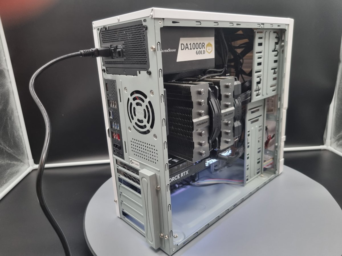
The Hibernator Build
AlmightyWaffles posted a topic in PC Giveaway Community's Build Log & Education
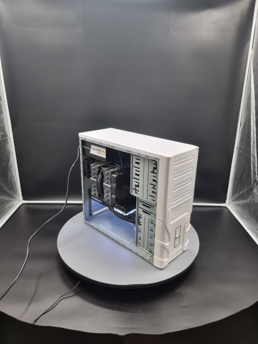
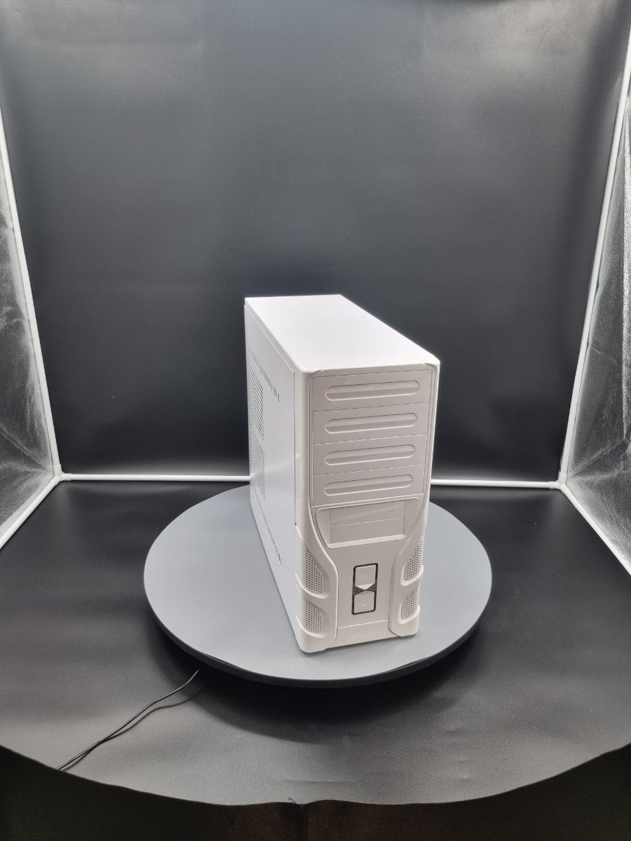
Alright guys, so first time posting in here, just want to state that the hibernator PC was a hoot to build, and here's a step by step guide to what I did to make this PC. I hope people enjoy the read as much as I enjoyed the write. Step 1 - I started by lining up where the motherboard standoffs go, due to it being an older case bought second hand, it didn’t include them, so I also had to grab some that I had sitting around. Step 2 – I grabbed the motherboard out and sat it on its box. Step 3 - I then grabbed out the CPU from the box, then I opened the CPU socket on the motherboard, by lifting up the socket lever. I then lined up arrow on the CPU socket and the arrow on the CPU itself, and I placed the CPU down, then I pulled the lever down which released the socket cover from its slot. Step 4 – Next we have the ram to install, which just meant open the box and pull the four sticks of 16gb ddr5 ram, made sure the notch lines up and then installed them one by one. Step 5 – I removed the m.2 cover from the motherboard using the clip on the motherboard, installed the 4tb m.2 into the primary slot, after that I removed the plastic from the thermal pads included on the m.2 cover and then put the cover back on Step 6 - Then I removed the plastic cooler brackets from the Motherboard and installed the brackets that were needed for the Forza 135 Dual Air Tower Cooler. Step 7 – After the cooler brackets are in place, I grabbed the case and had to remove an old cpu cooler air guide from the side panel. Step 8 – Now it’s time to install the motherboard into the case, and this motherboard has the I/O shield attached to the board, so no need to install that first. Then I screwed the motherboard down. Step 9 – Once the motherboard is in place, it was time to install the cooler, so we started by pasting the cpu with a x shape (my own preference), then I removed the plastic film from the heatsink and installed it onto the CPU socket. Step 10 – Then I grabbed out the power supply, and installed it with the four included screws. Step 11 – After that, I installed the two fans onto the tower cooler, with the 120mm fan on the outside, and the 140mm fan on the inside. Mounting them with the included clips to do so. Step 12 – Time to install the graphics card. So, I grabbed out the GPU from the box, installed it into the appropriate slot and screwed it down with the 2 necessary screws. (As mentioned earlier, this was a second hand case, so the PCI-E slot covers were already removed) Step 13 – I then installed the back case fan with the four necessary screws. Step 14 – Alright so at this point I then grabbed out my g-connector that was included with the motherboard, and installed my front I/O cables into the correct slots, then I plugged the g-connector into the correct spot on the motherboard Step 15 – At this point I have had to back track a bit, and pull out the tower cooler, as there was not enough room to fit my hand in to get the 8 pin motherboard connector into its slot. Once the tower cooler was removed I grabbed my 8-pin, 24-pin and my 12V2x6 / 12VHPWR (16-pin) cables from the power supply box. Connecting them to the power supply and then to the motherboard and graphics card. Step 16 – Now, I quickly grab a power cable and plug the computer in and test that it turns on with no errors. Once I know it turns on with no errors, I turn it off really quickly and reinsert the cooler onto the CPU. Step 17 – Now we are at the stage of cable managing, so I rerouted as many cable as possible into neat channels, and use tie downs to make it look as neat as possible.