
Overview
About This Club
- What's new in this club
-

Hibernator PC
Cat_Dad8311 replied to Cat_Dad8311's topic in PC Giveaway Community's Build & Technical Help
Yep as soon as I can I'll go and pay the 70 something for the labor and pick it up probably be a few days not feeling very well has been a pretty crappy birthday and look at how I can set it on my desk and make sure kitty cats don't want to try and reach in the case since it won't have that panel on it -

Hibernator PC
Macsusc replied to Cat_Dad8311's topic in PC Giveaway Community's Build & Technical Help
@AlmightyWaffles hey I thought you tested the clearance and I remember in the youtube build video it had about 3mm? Is it possible the side panel was bent during shipping or something like this? either way, it's good that it works! Happy to cover the cost of the inspection 🙂 Now you finally have a PC! -
Hibernator PC
Cat_Dad8311 replied to Cat_Dad8311's topic in PC Giveaway Community's Build & Technical Help
Okay so they called back he finally got it to boot up after taking it apart he says he can get it to work he has to get the cooler back on says the lroblem.is the case is too small with the cooler so when the side panel is on it presses the cooler fan and it keeps upsetting the ram so her said he may be able to get it to where its not bent and works but wont be able to put a side panel on it and ge will call m2 back when they are done done with cost and ect -
 Faisalhabib joined the club
 -
Hibernator PC
Cat_Dad8311 replied to Cat_Dad8311's topic in PC Giveaway Community's Build & Technical Help
Okay and thank you the pc is at pc quest here where I live he said that it may be a day or 2 but when he figures out whats up he we email me the fix needed and that way and can send that to you guys to make decisions and go from there and thank you -
Hibernator PC
Macsusc replied to Cat_Dad8311's topic in PC Giveaway Community's Build & Technical Help
I've sent you some money through PayPal to get it checked out, let me know how it goes 🙂 -
 SAOBlank joined the club
 -
Hibernator PC
Cat_Dad8311 replied to Cat_Dad8311's topic in PC Giveaway Community's Build & Technical Help
So yeah tomorrow I'll call some places best buy wanted a 100 bucks just to look at it and all he kept doing was sign up for our card for geek support so yeah they can suck a big toe. We have a couple local places I want to find one that will let us know what's wrong what needs to be done and then go from there not pay 100 to 200 just to get an answer dumb asses lol -
Hibernator PC
Cat_Dad8311 replied to Cat_Dad8311's topic in PC Giveaway Community's Build & Technical Help
I can make an appointment and drop it off with them and it happens i remember man this has been 20 years ago I had a pc built and the person that built it had something similar happen but its usually for me lmao if its that one weird 1 percent thing that can happen ill find it -
Hibernator PC
Cat_Dad8311 replied to Cat_Dad8311's topic in PC Giveaway Community's Build & Technical Help
Yeah it booted up and I feel like it did a bios update but I didnt read what the update was before bed and tomorrow ill download the manual again and no I dont want any parts ordered for it cause im not the right person to know really what im doing right now so probably best just to leave it be -
Hibernator PC
Macsusc replied to Cat_Dad8311's topic in PC Giveaway Community's Build & Technical Help
Hey @Cat_Dad8311 can someone take it to the geek squad for you? Let us cover the cost for it. I really don't like how this is happening, let's get this working properly. -
 bueforeal joined the club
 -
 Yojohobo joined the club
 -
Hibernator PC
Cat_Dad8311 replied to Cat_Dad8311's topic in PC Giveaway Community's Build & Technical Help
Now it has a boot light and the ram light on just the one stick of ram in it after trying all of it I'm really afraid I'm just going to make it worse now I have another light I'm just gonna stop maybe one day when and if I ever get healthy and can work again I'll take it to like a best buy geek squad but if I keep touching it it will get worse everything I touch does
-
Hibernator PC
Cat_Dad8311 replied to Cat_Dad8311's topic in PC Giveaway Community's Build & Technical Help
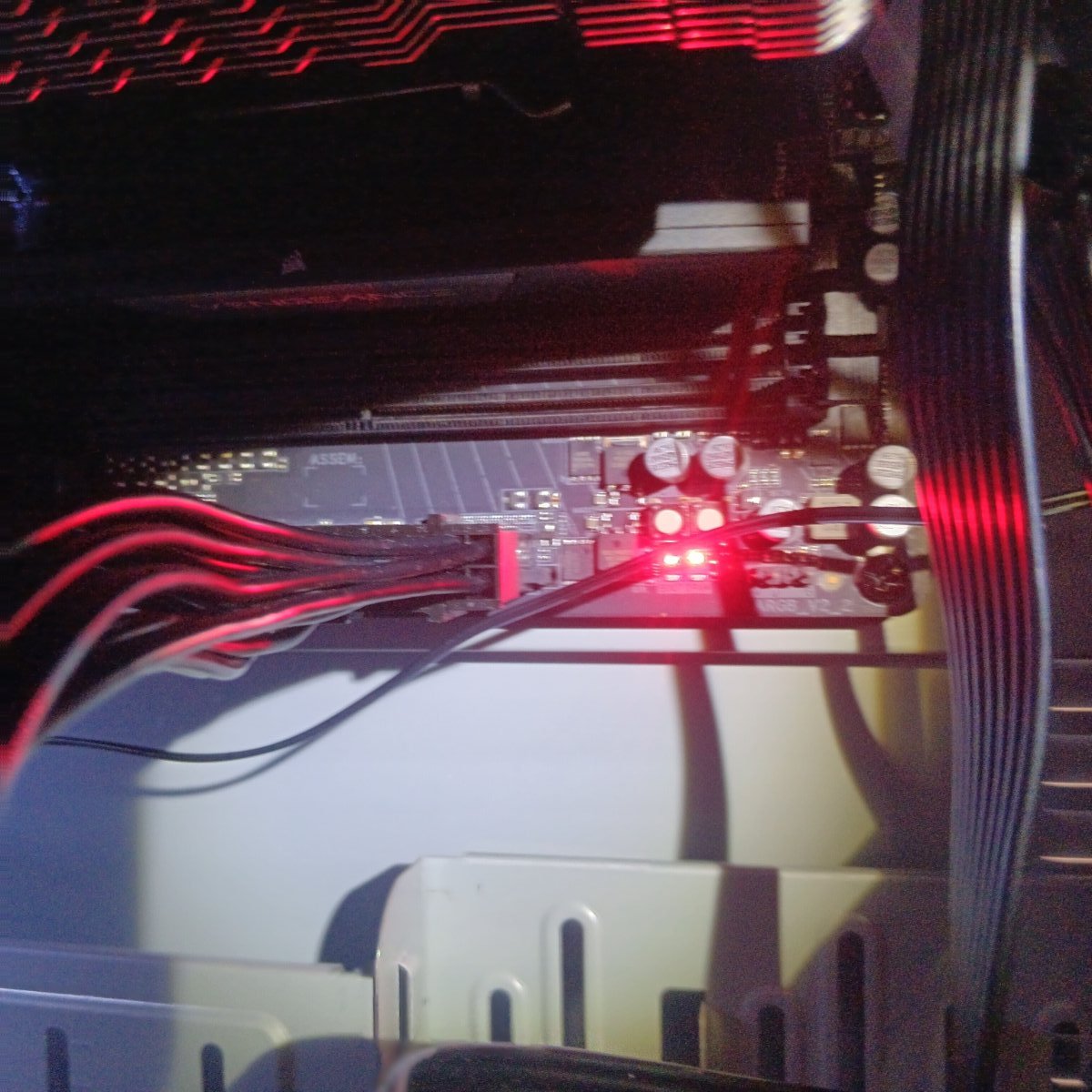
Right now I put the flash drive on now ram in and hit the flash button the PC came on and it's flashing on the back so I'm hoping that's the flash doing its thing after it stops I'll clear the cmos again put in one stick in A2 and boot then take a pic of it -
Hibernator PC
Cat_Dad8311 replied to Cat_Dad8311's topic in PC Giveaway Community's Build & Technical Help
Okay so the Motherboard says A2 and B2 i tried that I haven't tried taking out all the ram and clearing the cmos and then doing the flash putting in just one stick in a2 and try that so going to do that next and ill update and see what happpens -

Hibernator PC
AlmightyWaffles replied to Cat_Dad8311's topic in PC Giveaway Community's Build & Technical Help
I 100% agree with @Macsuscassumptions. Those are the exact steps I would undertake to try to rectify this issue. @Cat_Dad8311Honestly mate, there's no need to worry. Nothing on a PC can't be repaired or replaced. Sometimes it takes a few steps to ascertain the exact issue, but we will figure it out and get this PC going for you. -
Hibernator PC
Macsusc replied to Cat_Dad8311's topic in PC Giveaway Community's Build & Technical Help
If the above does not work. Then we do this Do This Exactly Step 1: Download Latest BIOS On another computer: Go to Gigabyte support page for B850 AORUS ELITE WIFI7 Download latest BIOS Extract file Rename BIOS file to: GIGABYTE.bin (Required for Q-Flash Plus) Step 2: Prepare USB Format USB to FAT32 Copy only the renamed BIOS file to root Step 3: Flash BIOS Turn PC off Leave PSU plugged in and switched ON Insert USB into the white Q-Flash USB port (rear I/O) Press the Q-Flash Plus button The small LED should start blinking. Do NOT interrupt. Wait until blinking stops completely. Step 4: After Flash Completes Clear CMOS again Install one RAM stick in A2 Boot Since the computer was booting before, what may have happened is during your windows update, you either had the PC turn off due to a power surge or someone turned it off or it corrupted the BIOS for some othe reason. If we re install the bios and clear the cmos and it still does not run, I think we need to get either a new CPU or new ram sticks. -
Hibernator PC
Macsusc replied to Cat_Dad8311's topic in PC Giveaway Community's Build & Technical Help
Install just ONE stick in A2, second from the CPU cooler. While the PC is off. Then boot it up, send a pic of the motherboard at this time. If it doesn't boot, use the other ram stick in A2. -
Hibernator PC
Macsusc replied to Cat_Dad8311's topic in PC Giveaway Community's Build & Technical Help
Can you take a photo of the ram sticks and the positions they are seated in? They should be in A2 and B2 -
Hibernator PC
Cat_Dad8311 replied to Cat_Dad8311's topic in PC Giveaway Community's Build & Technical Help
Yeah it booted up and I feel like it did a bios update but I didnt read what the update was before bed and tomorrow ill download the manual again and no I dont want any parts ordered for it cause im not the right person to know really what im doing right now so probably best just to leave it be -
Hibernator PC
Macsusc replied to Cat_Dad8311's topic in PC Giveaway Community's Build & Technical Help
@Cat_Dad8311 do not give up, everything in life takes a bit of effort, this type of stuff happens to everyone, we just need to get through it together and we will. We can order you new RAM we just need to confirm that the RAM is dead, the computer initially booted up for you and went into a Windows update correct? It is very strange that the RAM would have suddenly had a fault after this. We just need to make sure that the RAM 100% needs to be replaced before we make the order for you. Can you confirm that you were taking the RAM out and reseating it with the computer OFF before turning it ON again? @AlmightyWaffles can you please double check the motherboard manual to confirm which slots the RAM should be seated in? Also check the manual for any other reasons the DRAM can be lighting up. -
 jeremiah_caspersen joined the club
 -
Hibernator PC
Cat_Dad8311 replied to Cat_Dad8311's topic in PC Giveaway Community's Build & Technical Help
I have tried each stick one at a time the light never changes ita really weird day one I got it to boot went to bed that night it said had to update before shutting down which is cool then the next morning when I tried turning it on thats what happened but to be honest thats the way it goes for me. I have the type of life that is all lemons lol but I appreciate the help but I think im just gonna call it for a bit. -
Hibernator PC
AlmightyWaffles replied to Cat_Dad8311's topic in PC Giveaway Community's Build & Technical Help
Next step would be 1. Test RAM Individually Remove all RAM sticks except one Try that single stick in each RAM slot one at a time If it works in one slot but not others, you may have a bad slot If none work with that stick, try a different stick If after trying both modules in every slot and the DRAM light is still not working, then it is a strong possibility there is something wrong with the RAM. However I still doubt this to be the issue, as RAM is usually a pretty solid component in a PC. -
 belkar13 joined the club
 -
Hibernator PC
Cat_Dad8311 replied to Cat_Dad8311's topic in PC Giveaway Community's Build & Technical Help
And thx for that one pic helped getting the fan off -
Hibernator PC
Cat_Dad8311 replied to Cat_Dad8311's topic in PC Giveaway Community's Build & Technical Help
Okay i did that also tried removing one at a time the light is still there -
Hibernator PC
AlmightyWaffles replied to Cat_Dad8311's topic in PC Giveaway Community's Build & Technical Help
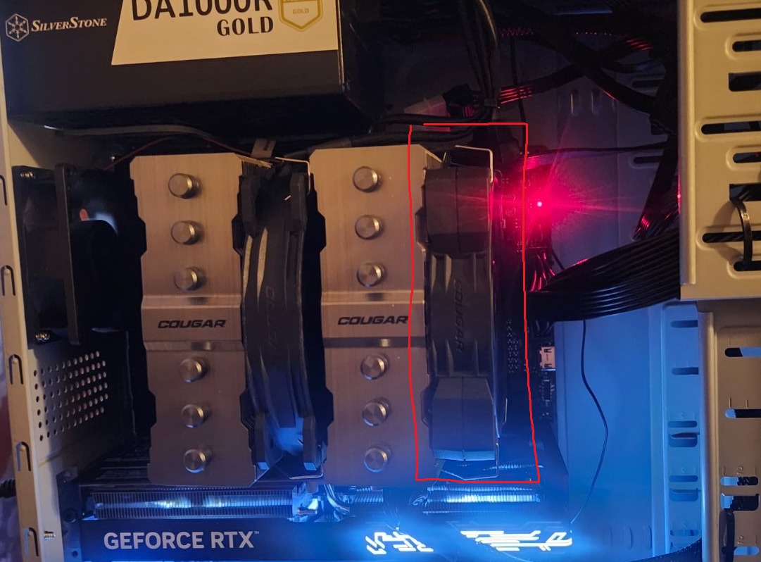
The DRAM indicator light signifies an issue with the RAM modules. As an initial troubleshooting step, I recommend reseating the RAM. Begin by removing the fan assembly shown in the image above. Next, locate the RAM sockets and press down on the retaining clips at the top of each socket to release the modules. Carefully remove the RAM sticks, noting their original positions. When reinstalling, ensure the pins on the modules align correctly with the socket notches. Apply firm, even pressure to seat the RAM until the retaining clips snap securely into place around the modules. -
Hibernator PC
Macsusc replied to Cat_Dad8311's topic in PC Giveaway Community's Build & Technical Help
Pop this fan off, you just need to pull the metal clamps on each side of it, should come off easily, you should see some ram under there
-
Hibernator PC
Cat_Dad8311 replied to Cat_Dad8311's topic in PC Giveaway Community's Build & Technical Help
And as far as the ram i think its behind the cooling fans and things and with my current health and condition im not gonna try and remove anything to get to it I have to many spams in my hands to trust myself