


How to Build a PC Step-by-Step (Beginner-Friendly Guide 2025)

How to Build a PC: Step-by-Step Guide for Beginners
Building your own PC might seem daunting, but it’s absolutely achievable with the right guidance. This PC building guide will walk you through how to build a PC for beginners in a clear, step-by-step manner. We’ll cover everything from preparing your workspace to a final step-by-step PC assembly checklist. By following along, you can assemble a computer that meets your needs and gain a better understanding of how each component fits together.
Table of Contents
-
Preparation: Tools, Parts, and Safety
-
Step 1: Install the CPU
-
Step 2: Install the CPU Cooler (and Thermal Paste)
-
Step 3: Install Memory (RAM)
-
Step 4: Install M.2 SSD or Other Storage
-
Step 5: Mount the Motherboard into the Case
-
Step 6: Install the Power Supply (PSU)
-
Step 7: Install the Graphics Card (GPU)
-
Step 8: Connect Power Cables & Front Panel
-
Step 9: Cable Management and Tidying Up
-
Final Pre-Boot Checklist
Preparation: Tools, Parts, and Safety
Before diving into the build, take time to prepare your workspace, tools, and components:
-
Choose a Suitable Workspace: Work on a large, clean, flat surface. Avoid building on carpet to minimize static electricity.
-
Gather Your Components: You should have a motherboard, CPU (processor), CPU cooler, memory (RAM), storage drives (SSD/HDD), graphics card, power supply (PSU), and a PC case. Double-check compatibility: the CPU must match your motherboard’s socket, the RAM type (e.g., DDR4 or DDR5) must match the motherboard, and the PSU should have adequate wattage for your GPU/CPU.
-
Have the Right Tools: The main tool you need is a Phillips #2 screwdriver for most screws. Optionally, have some zip ties for cable management, a pair of pliers or scissors to trim them, and a small flashlight or headlamp for tight spaces. An anti-static wrist strap can help prevent static damage (connect it to the PC case), or you can periodically ground yourself by touching the metal case.
Safety Tip: Always unplug the power supply from the wall before working on your PC. Never work on components with the system powered. Also, be mindful of sharp edges inside cheap PC cases – handle components and case interior with care to avoid cuts.
Compatibility Tip: Before assembly, verify that all parts are compatible. Ensure your motherboard fits your case (ATX, MicroATX, ITX, etc.), your PSU cables reach all components, and your graphics card can fit in the case (both length and width).
With everything ready and checked, let’s start building!
Step 1: Install the CPU
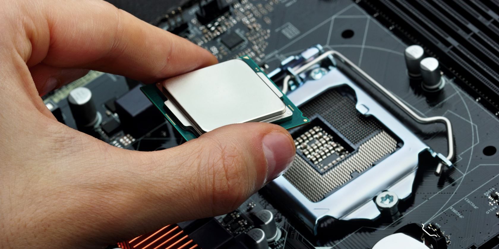
Installing the CPU into the motherboard socket.
Carefully take the motherboard out of its box and place it on your work surface (on top of the anti-static bag or foam it came with). Now get your CPU chip ready for installation:
-
Locate the CPU Socket: On the motherboard, find the square CPU socket which likely has a protective cover. There’s a small metal lever or latch on one side. Gently press down and lift the lever to open the socket’s retention bracket. Remove any plastic cover, revealing the socket pins or contacts.
-
Align the CPU: Notice a small gold triangle or arrow on one corner of your CPU. Find the matching triangle marker on the corner of the socket. Align these markers to orient the CPU correctly. This ensures the CPU’s pins (or pads) match the socket holes.
-
Insert the CPU: Holding the CPU by its edges (avoid touching the gold pins or contacts on the underside), lower it straight down into the socket. It should drop in place with zero insertion force – do not push or force it. If it’s aligned properly, it will sit flat in the socket.
-
Secure the CPU: Once the CPU is in place, lower the retention bracket back down. Press the lever back into place under its hook to lock the CPU. You may feel a bit of tension while locking it – that’s normal. If your socket had a cover, it will pop off as you close the lever (save it in your motherboard box in case you ever transport or RMA the board).
Safety Tip: Be extremely careful not to bend any pins in the CPU socket or on the CPU. Bent pins can prevent the PC from working. If the CPU isn’t dropping in easily, double-check alignment rather than forcing it.
Compatibility Tip: Make sure you have the correct CPU socket for your processor (for example, an Intel LGA1700 CPU won’t fit in an LGA1200 socket, and an AMD AM5 CPU won’t fit in an AM4 socket). Also, different sockets have different installation mechanisms (Intel uses LGA sockets with a lever, while many AMD CPUs have PGA pins and use a similar lever mechanism).
With the CPU firmly seated, you’re ready to move on to cooling it.
Step 2: Install the CPU Cooler and Thermal Paste


Your processor generates heat, so installing the CPU cooler properly is critical. There are two main types of coolers: the stock air cooler (often included with mid-range CPUs) or an aftermarket cooler (air or liquid). The installation can vary, so always refer to the cooler’s manual, but general steps are below.
CPU air cooler fan mounted on the motherboard, ready to cool the CPU.
-
Apply Thermal Paste: Most air coolers sit on the CPU with a metal base. To help transfer heat, you need a thin layer of thermal paste on the CPU. If your cooler already has thermal paste pre-applied (a gray square on its underside), you can skip this. Otherwise, squeeze a small pea-sized dot of thermal paste onto the center of the CPU’s top surface. (This will spread out when the cooler is mounted.)
-
Attach the CPU Cooler: Align the cooler over the four holes or mounting bracket around the CPU socket. Typically, stock Intel coolers have push-pins that go into the holes, while others use a bracket with screws. Gently place the cooler, and secure it per the manufacturer’s instructions:
-
For push-pin coolers: Twist the pins to the unlocked position if required, then insert each pin into a hole and press down diagonally opposite pins (e.g., top-left, then bottom-right) until they click. Then do the other two. Verify all four are fully engaged.
-
For screw-mounted coolers: Thread each screw a few turns, going in a cross pattern (tighten one corner a bit, then the opposite corner, etc.) to apply even pressure. Then tighten all the way, but do not overtighten – snug and firm is enough.
-
-
Connect the Fan Cable: Locate the small wire coming from the cooler’s fan. Plug it into the CPU_FAN header on the motherboard (a 3- or 4-pin connector usually near the CPU socket). This powers the cooler’s fan. It should click into place; make sure it’s secure.
Safety Tip: When applying thermal paste, less is more. A small dot is enough – too much paste can spill over and act as an insulator or cause a mess. If you ever need to redo it, clean off the old paste with isopropyl alcohol and a lint-free cloth before reapplying.
Compatibility Tip: Ensure your cooler is compatible with your CPU socket. Many aftermarket coolers include different mounting brackets for Intel vs. AMD. Use the correct parts for your socket (e.g., AM4 bracket for AMD AM4 socket, LGA1700 standoffs for Intel 12th-gen, etc.).
Now your CPU is installed and cooling in place – next up is memory.

Step 3: Install Memory (RAM)
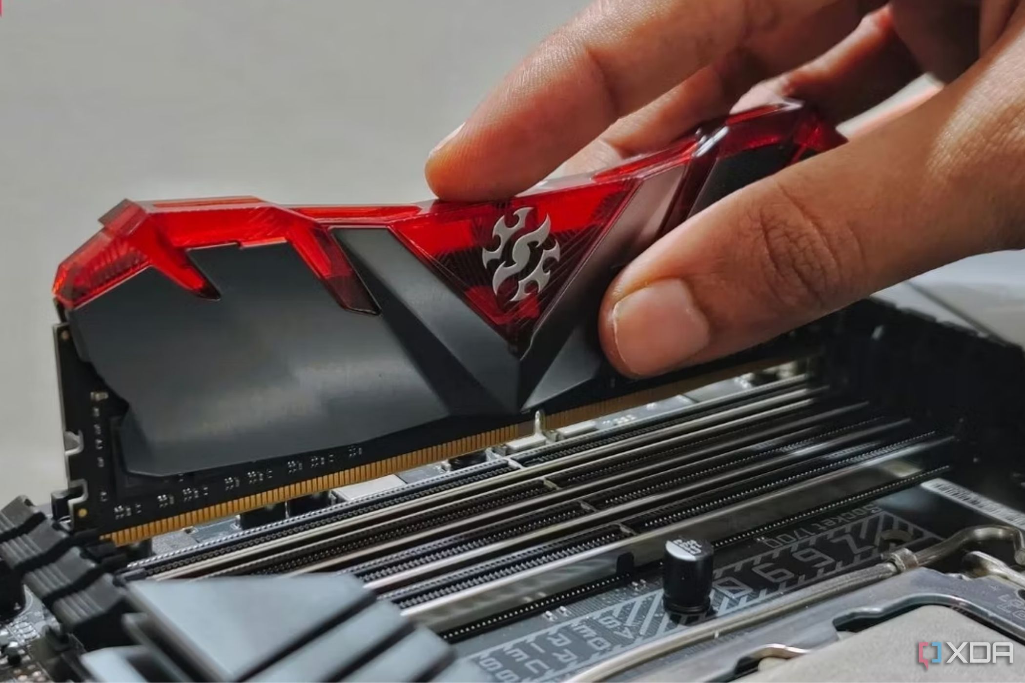
Installing your RAM (Random Access Memory) is one of the simpler steps in PC assembly. RAM modules (DIMMs) are long sticks that click into the motherboard’s memory slots.
-
Locate the RAM Slots: Find the long slots on the motherboard, usually near the CPU. Most modern boards have 2 or 4 memory slots. If the slots have two different colors (paired), that indicates the channels. Check your motherboard manual for the recommended slots to populate first (for dual-channel, usually slot 1 and 3, or 2 and 4).
-
Open the Slot Latches: At either end of each RAM slot, there’s a small plastic latch/clip. Open these by pressing them outward (they may already be open on one side, depending on the board design).
-
Align the RAM Stick: Notice the notch in the gold pins of the RAM module – it’s off-center. Align that notch with the bump in the motherboard slot. This ensures you orient the RAM correctly (it only fits one way).
-
Insert the RAM: Place the module into the slot, making sure it’s lined up. Using your thumbs, press down firmly and evenly on both ends of the RAM stick. You’ll feel it snap in as the latches on the sides click up into the notch on the RAM. If the latches didn’t fully engage, press a bit more until they do. Repeat for additional RAM sticks.
A PC builder installing components and connecting cables inside a PC case (note the already-installed RAM and CPU cooler).
Troubleshooting Tip: If a RAM module isn’t fully clicking in, remove it and check for any obstructions. Ensure the notch is aligned and try again with steady pressure. It can require more force than you expect, but always press straight down – don’t wiggle or angle it.
Compatibility Tip: Make sure you’re using compatible RAM. The motherboard will specify DDR4, DDR5, etc., and you must use that type. Also, mixing different RAM capacities or speeds can sometimes cause issues, so for best results use a matched kit (same size and speed).
With memory installed, the core of the motherboard (CPU, cooler, RAM) is ready. If you have an M.2 SSD, install it before mounting the motherboard in the case, as it’s easier to do now.
Step 4: Install M.2 SSD or Other Storage
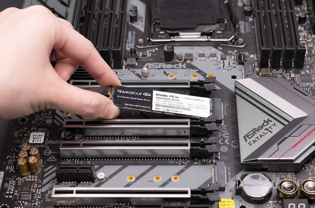
Most modern builds use an M.2 SSD (a gumstick-sized solid state drive) that mounts directly on the motherboard, and/or 2.5” SATA SSDs or 3.5” hard drives that mount in the case. We’ll handle M.2 now and other drives later once the motherboard is in the case.
-
M.2 SSD (On Motherboard): Locate the M.2 slot on the motherboard (a small slot usually between the PCIe slots or near the SATA ports). If it has a heatsink cover, unscrew and remove that first. To install the M.2 drive:
-
Remove the tiny screw at the end of the M.2 slot (don’t lose it!).
-
Align the M.2 SSD’s connector with the slot and insert the drive at about a 30-degree angle. Push it in until fully seated.
-
Gently press the drive down flat to the standoff on the motherboard. Secure it with the screw you removed. (Do not overtighten this tiny screw.)
-
If your board has a heatsink for the M.2, remove any plastic film from its thermal pad and screw the heatsink back on over the drive.
-
-
2.5” or 3.5” Drives (SSD/HDD): If you have a SATA SSD or HDD, you will mount these inside the case, typically in dedicated drive bays or trays. At this stage, you can plan where they will go, but it’s often easier to mount them after the motherboard and PSU are in (so you can see cable lengths). We will cover drive mounting in a later step when connecting cables.
Compatibility Tip: If using an NVMe M.2 SSD, ensure the M.2 slot supports NVMe PCIe drives (most do) and that installing an M.2 doesn’t disable any SATA ports (some motherboards share bandwidth between M.2 and SATA). Check your manual if unsure.
Now that CPU, cooler, RAM, and possibly M.2 storage are on the motherboard, it’s time to put the motherboard into the case.
Step 5: Mount the Motherboard into the Case
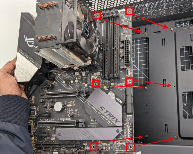
Preparing the case and installing the motherboard is a crucial step. Take your time and handle the board by its edges.
-
Prep the Case: Remove both side panels of your PC case (usually thumb screws or Philips screws at the back). Lay the case on its side so the open motherboard tray faces up. Make sure the motherboard standoffs (small brass spacers) are installed in the case’s motherboard tray in the holes that correspond to your board’s form factor (ATX, MicroATX, etc.). The standoffs keep the board raised and prevent short-circuits. Cases usually come with standoffs pre-installed or included separately. Install or rearrange them if needed so that each screw hole in the motherboard has a standoff underneath.
-
Insert the I/O Shield: If your motherboard came with a separate I/O shield (the rectangular plate with cutouts for the rear ports), snap that into the rectangular hole at the back of the case. It should click in all four corners. Be careful of the metal tabs on the shield – make sure they aren’t bent in a way that will block the motherboard’s ports.
-
Position the Motherboard: Hold the motherboard by the edges and gently lower it into the case. Align the board so that its ports fit through the I/O shield and the screw holes line up with the standoffs. It can help to tilt the board slightly to get the ports through the I/O shield first, then lay the board down on the standoffs.
-
Screw in the Motherboard: Using the screws that came with your case (or motherboard), screw the motherboard down onto each standoff. Typically there are 6-9 screws. Start each screw lightly to make sure it’s not cross-threaded, then tighten them just until snug. Do not over-tighten (you can crack the board or strip the threads) – just secure enough that the board doesn’t move.
Safety Tip: Double-check that there are no extra standoffs under the motherboard in the wrong place. An extra standoff touching the back of the board where it shouldn’t can short out and damage components. Only the holes that line up with the board should have standoffs.
Troubleshooting Tip: If the screw holes don’t line up, verify you have the correct standoff positions for your board. You might need to slightly adjust the board’s position or the I/O shield alignment. Also ensure no cables are caught underneath the board.
Now the motherboard is securely in the case. Next, we’ll install the power supply that will power all these components.
Step 6: Install the Power Supply (PSU)
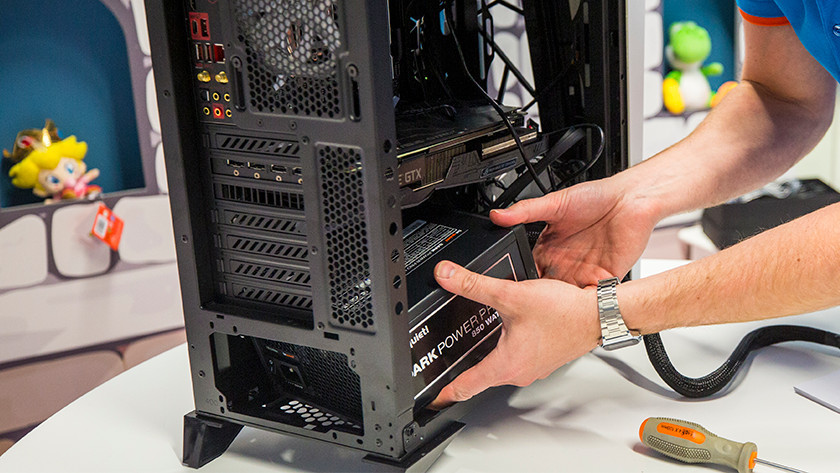
The PSU (Power Supply Unit) typically goes in the bottom rear of modern cases (or top rear in some older designs). It provides power to all components, so proper installation and connecting the correct cables is important.
-
Position the PSU: If your case has a bottom PSU mount, orient the PSU with its fan facing downward (if the case has a vent at the bottom) or upward (if no bottom vent or if on a carpeted floor). Slide the PSU into the case from the side or rear (depending on case design) until its screw holes at the back align with the case’s holes.
-
Secure the PSU: Using the four screws that came with the PSU (or case), fasten the PSU to the case’s rear panel. These screws go in the four corners of the PSU from the outside back of the case. Tighten them snugly.
-
Cable Planning: If your PSU is modular (cables detach), now is a good time to plug in the cables you’ll need: typically the 24-pin ATX cable (for motherboard), 8-pin EPS cable (for CPU power), PCIe power cables (for graphics card), SATA power cables (for drives), etc. If it’s a non-modular PSU, you’ll have a bundle of all cables already attached. Route the cables out of the way for now – you can push them through to the back side of the case if you have a cable management cutout. We will connect them in the next steps.
Compatibility Tip: Ensure your PSU has enough wattage for your build. A quality 500W–750W unit covers most mid-range builds, but high-end systems with powerful GPUs might require 800W or more. It’s also important that the PSU has the necessary connectors (an 8-pin EPS for CPU, PCIe 8-pin plugs for your GPU, etc.).
With the PSU in place, you have the “engine” ready to power the system. Now, let’s add the graphics card (if you have one) and then hook everything up.
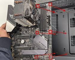
Step 7: Install the Graphics Card (GPU)
.JPG?width=1920&height=1920&fit=bounds&quality=70&format=jpg&auto=webp)
If you’re using a dedicated graphics card, install it now while the case is still open and roomy. If you’re using integrated graphics and have no GPU card, you can skip this step.
-
Prepare the Slot: Identify the top PCI Express x16 slot on your motherboard (that’s where the GPU goes, usually the reinforced longest slot). On the back of the case, you’ll need to remove 1 or 2 expansion slot covers corresponding to that slot (the metal strips blocking the case openings where the GPU’s ports will go). These are either unscrewed or snapped out. Remove the correct ones so the GPU’s output ports will be accessible from the back.
-
Slot the GPU In: Hold the graphics card by its edges (and metal bracket). Align the gold PCIe fingers with the motherboard’s PCIe slot. Also make sure the card’s rear bracket lines up with the open slots at the back of the case. Push the card straight into the slot firmly until you hear/feel the click of the slot’s latch securing the card. The card’s gold fingers should be mostly or fully inside the slot.
-
Secure the GPU: Use the screws (from the case) to screw the GPU’s bracket to the case on the expansion slot area. This usually involves 1 or 2 screws through the bracket into the case frame. Tighten them to hold the card in place.
-
Connect PCIe Power (if required): Most modern GPUs need external power from the PSU. Locate the PCIe power connectors on the card (6-pin, 8-pin, or multiple). We will connect the appropriate PSU cable to these soon, but you can already route the correct PSU cable to the card’s vicinity.
Safety Tip: Support the graphics card’s weight as you install it, especially big heavy cards. Make sure it is sitting level in the slot and not sagging significantly. All screws and latches should be secured to prevent the card from moving.
Troubleshooting Tip: If the card doesn’t slot in, check if any obstruction in the case (drive bays, etc.) is hitting it, or if the slot covers removed were the wrong ones. Also ensure the slot’s latch at the end is open (some need to be pushed aside first) before inserting the card.
Now your major components are all installed in the case. The final assembly steps are connecting all the power and data cables and then tidying up the wiring.
Step 8: Connect Power Cables & Front Panel
This step is all about wiring your PC. You will connect the power cables from the PSU to the motherboard and other components, as well as the front panel connectors (power button, USB ports, etc.) from the case to the motherboard.
1. Motherboard Power (24-pin ATX): Take the largest cable bundle from the PSU – the 24-pin connector – and plug it into the 24-pin socket on the motherboard (usually on the right-hand side). It only fits one way (a clip on the side of the plug will latch onto a notch on the socket). Press it in firmly until the latch clicks. This cable powers the motherboard.
2. CPU Power (EPS 8-pin): Plug in the 8-pin (or 4+4 pin) EPS connector from the PSU to the motherboard’s CPU power header, which is usually near the top-left of the board, by the CPU. Again, it has a clip that latches; ensure it’s fully seated. This powers the CPU.
3. GPU Power: If your graphics card requires power connectors (6-pin, 8-pin, or multiple), plug the corresponding PCIe power cable(s) from the PSU into the GPU. They usually clip in from the side or top of the card. Make sure each is firmly connected. (If the GPU has no external power connectors, it draws all power from the slot, so no PSU cable needed here.)
4. Storage Drive Cables:
-
For 2.5”/3.5” SATA drives: Connect a SATA power cable from the PSU to each drive (the thin wide L-shaped connector). Then attach a SATA data cable from each drive to a SATA port on the motherboard (also an L-shaped connector, smaller than power). SATA data cables typically came with your motherboard.
-
For the M.2 SSD: No cables needed, since it’s already in the slot.
Make sure any drives are also physically secured in the case’s drive bays or trays (screw them in or latch them according to the case design if you haven’t already).
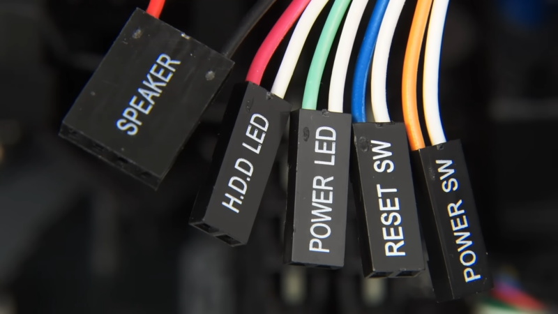
5. Case Front Panel Connectors: These are a bundle of small wires from the case’s front: usually labeled PWR SW (power switch), RESET SW (reset switch), PWR LED (power LED), HDD LED (drive activity LED), etc. Refer to your motherboard’s manual for the front panel header pin layout (often called “F_PANEL”). Plug each wire’s small two-pin connector onto the correct pins. This part can be fiddly – use tweezers or good lighting if needed. The labels on the connectors correspond to labels on the motherboard’s front panel block. (Tip: The writing on each connector typically faces upward or toward the outside of the pins.)
6. Case USB/Audio Connectors: If your case has front USB ports or audio jacks, connect those as well: -
USB 3.0 connector: A thick cable with a 19-pin block – plugs into a matching large header on the motherboard (often blue plastic inside). Align it carefully (it only fits one way due to a missing pin).
-
USB 2.0 connectors: One or more small 9-pin plugs (often labeled like “USB1”) that go into 9-pin headers on the board. These also have a keyed pin – align and push in.
-
Front Audio (HD Audio): A cable labeled HD_AUDIO (or AC’97) which plugs into the motherboard audio header (usually bottom left area of the board). Align the missing pin and press it in.
Compatibility Tip: Sometimes cables can reach their destination only via certain routes in the case. Use the cutouts in the case (cable management holes) to run cables behind the motherboard tray and out where they need to plug in. This keeps the build cleaner and ensures cables aren’t stretched too tight. For example, front panel connectors often route through a bottom cutout to reach the header, and EPS CPU power cable might route behind the board to the top.
At this point, every component should be installed and connected. Next, we’ll tidy up the cables for better airflow and aesthetics.
Step 9: Cable Management and Tidying Up

A tidy build is not just about looks – it also helps airflow and future maintenance. Cable management involves routing and securing excess cables so they don’t obstruct fans or interfere with components.
-
Gather Excess Cable Length: Behind the motherboard tray (the right side of the case if looking from front) is the usual spot to tuck away extra cable length. Gently pull the slack of each cable to the back. For example, extra PSU cable length and SATA cable slack can reside here.
-
Use Zip Ties or Velcro Straps: Most cases provide tie-down points (little loops or slots) on the back tray. Bundle related cables together and use zip ties or reusable Velcro straps to secure them to these points. For instance, tie the 24-pin and EPS cables together neatly, and bunch SATA power leads together. Trim off excess from zip ties.
-
Keep Cables Clear of Fans: Make sure no cables are dangling into any fan blades (CPU cooler fan, case fans, GPU fans). Use additional ties to anchor cables away from any spinning fans.
-
Front Side Neatness: On the main component side, try to route cables along edges and corners. For example, route the GPU power cable along the case’s side or behind the card, rather than across the middle. Tuck the front panel wires down low and behind things so they aren’t hanging loose.
-
Install Side Panels: Once everything is tied down, gently put the back side panel on—ensure no bulging cables are in the way. It might take a bit of pressure if there are many cables, but if you have major difficulty, recheck and flatten any stubborn cable bundles. Then put the main clear/acrylic side panel back on to close up the case.
Your PC build is now assembled! Before we hit the power button, let’s run through a final checklist to verify everything.
Final Pre-Boot Checklist
Before powering on your new PC for the first time, go through this checklist to ensure nothing was missed:
-
All Components Installed: CPU (with cooler) ✔️, RAM ✔️, Motherboard ✔️, PSU ✔️, GPU (if any) ✔️, Storage drives ✔️.
-
All Screws Tightened: Motherboard screws, PSU screws, GPU bracket screw, and any drive mounting screws are secured. (Not overly tight, just snug.)
-
Power Cables Connected: 24-pin ATX to motherboard, 8-pin CPU power to motherboard, PCIe power to GPU, SATA power to drives.
-
Data Cables Connected: SATA data cables from drives to motherboard, front panel USB 3.0/2.0 cables, front audio cable, etc., all firmly attached.
-
Front Panel Wires Connected: Power switch at minimum is connected (so you can turn the PC on), as well as reset switch, LEDs, etc., in the right pins.
-
CPU Cooler Fan Connected: CPU fan (and any case fans) are plugged into the appropriate motherboard headers or fan controller.
-
No Loose Objects: Tools, extra screws, or brackets are not accidentally left inside the case. Also, no loose cables near fans.
-
External Connections Ready: Plug in your monitor cable to the GPU (or motherboard video out if no GPU), and connect keyboard and mouse. Attach the power cord to the PSU and plug it into the wall. (Ensure the PSU switch is off [O] when plugging in.)
Everything looks good? Double-check that PSU is switched off, then turn on the PSU switch ([-]). Now moment of truth: press the PC’s power button. If all has been done correctly, your new PC should spring to life – fans spinning, lights on. 🎉
Bonus Tip: On first boot, if you see nothing on screen, don’t panic. Check that the monitor is on the right input and connected. If still nothing, turn off and recheck the above connections (especially the power cables and RAM/GPU seating). Common issues are a loose power connector or RAM not fully clicked in.
Once you see the BIOS/UEFI screen, you have successfully built your PC! From here, you can insert your OS installation media (like a USB drive for Windows or Linux) and proceed to install your operating system. Congratulations on completing this step-by-step PC assembly for your custom build! Enjoy your new PC and the satisfaction of having built it yourself.
0 Comments
Recommended Comments
There are no comments to display.
Please sign in to comment
You will be able to leave a comment after signing in
Sign In Now